3D Printer Issues: Accuracy of Thin Walls
Published: 2021-12-20
3D printers can be pretty accurate. How accurate depends on lots of factors, of course, but usually it's not a problem to create relatively tight-fitting mechanical parts. How can it happen then, that the thickness of thin walls can be way off?
Let's look at an example. It's just a ring with a thin wall (0.6mm thick).

Nothing wild so far. Let's print it!
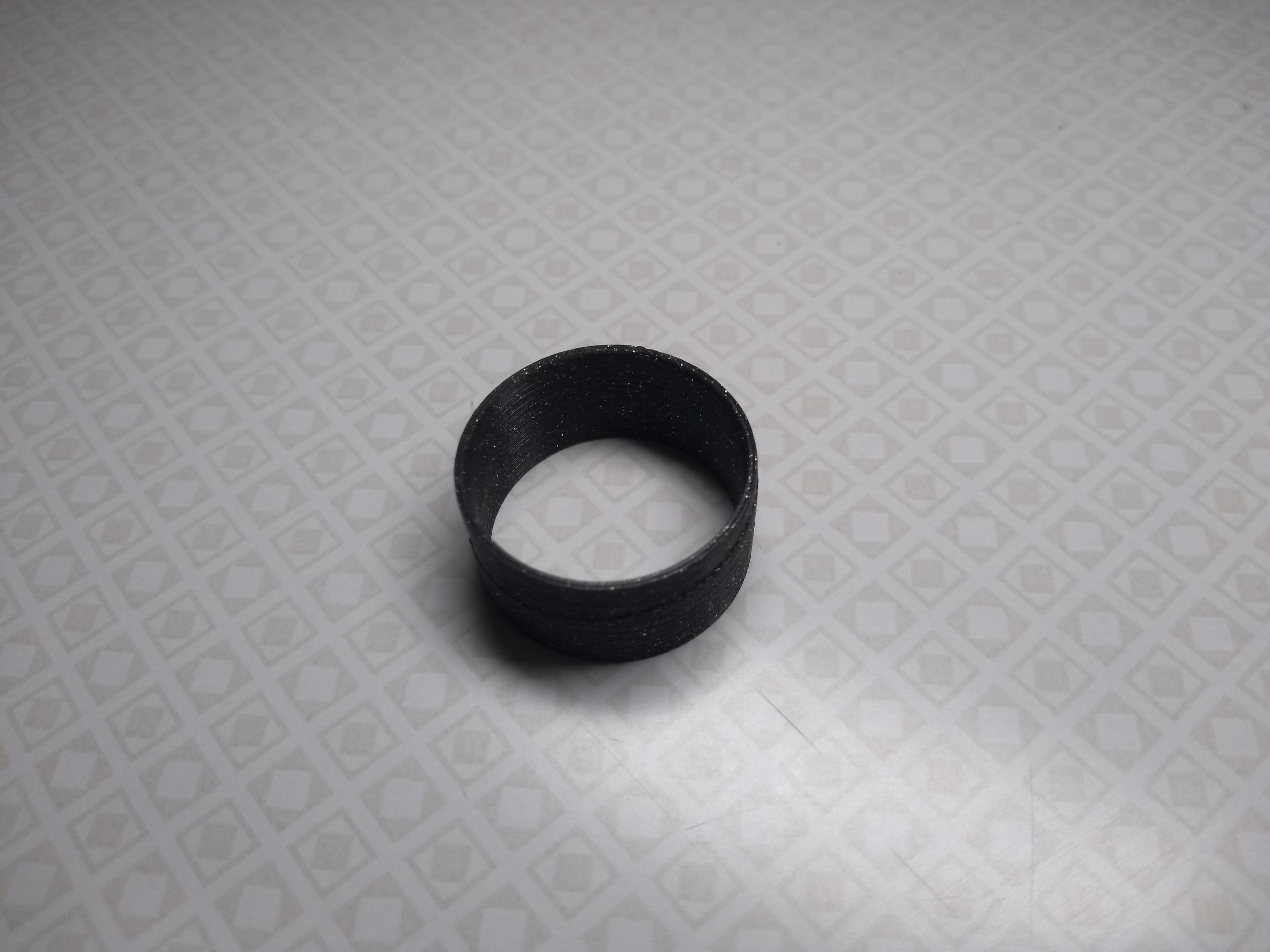
Looks reasonable. Let's measure the wall thickness.

What's this? The wall is 0.9mm thick! Why such a large deviation?
So what happened?
While this is the kind of thing that can drive you crazy for extended periods of time (well, at least that's what happened to me), it's actually pretty straight-forward: The wall is supposed to be 0.6mm thick. The printer has a 0.4mm nozzle. In the print settings, the extrusion width for perimeters is set to 0.45mm.
One perimeter with 0.45mm thickness would be thinner than the 0.6mm specified for the wall thickness. So the slicer decides to use two perimeters. Two times 0.45mm is 0.9mm. Which is exactly the value we measured.
Understanding the issue
When printing walls, neighboring perimeters are laid out next to each other, without a gap between them. That means that the total width of multiple perimeters is always going to be a multiple of the extrusion width.
This is not the case, if the perimeters are not directly next to each other. In thicker walls, there would typically be a few perimeters on each side, then some infill in the middle. Since the width of the infill doesn't depend on the extrusion width, we would not be running into the same issue then.
This is important to understand: This problem only shows up, if there are perimeters side by side, and the wall thickness is not a multiple of the extrusion width of those perimeters. This gives us some hints on how to prevent this issue from bothering us.
Please note that, while we're looking at a thin wall here, this is not the only case where this issue can appear. Think, for example, about some small feature protruding from a larger print. As long as the slicer doesn't generate any infill within that feature (i.e. its thickness is defined by perimeters), it's going to be affected by this problem.
So how to fix it?
1. Change wall thickness to a multiple of the extrusion width.
If we have the freedom to change the dimensions in our model, we can just make the wall thickness a multiple of the perimeter extrusion width. If the wall thickness in my example model had been 0.9mm in the first place, we wouldn't have noticed a problem.
2. Make the wall thicker.
Again, if we can change the dimensions in our model, we can just make the wall so thick that it no longer just contains perimeters, but infill too. Then the slicer can adapt the width of the infill to achieve the desired wall thickness.
3. Reduce the number of perimeters.
This won't help, if we just have two perimeters, as in the example I've shown here. But if we have a slightly thicker wall with more perimeters, we can adjust the print settings and reduce the minimum number of perimeters. This will result in infill being generated in the wall, thereby sidestepping this problem.
Please note that with fewer perimeters, the wall will be weaker. This might or might not be acceptable, depending on the model.
4. Fiddle with the extrusion width.
If there's only a slight gap between the actual and desired dimensions, maybe we can fiddle with the extrusion width in the print settings to get a match. This has limits, however. We can't just set the extrusion width to a value that's completely different than the width of the nozzle.
I haven't tried this idea, so I don't know how much of a difference between nozzle and extrusion widths we could get away with. But it might be worth a try, in some situations.
5. Use a different nozzle.
With a smaller nozzle, we'll have a smaller extrusion width. This doesn't eliminate the problem, but the increased resolution might make it easier to get things to work. Especially, if we combine this measure with the other ideas presented here. A smaller nozzle would lead to longer print times, however, so it's a trade-off.
We could even use a larger nozzle, in some cases! In the example I showed here, we have a 0.6mm wall. This would be straight-forward to achieve with a 0.6mm nozzle. We'd have to deal with the lower resolution in the rest of the model too, though, so again, it's a trade-off.
Any other ideas?
Do you have any other ideas that I should present here? If so, let me know! I'm happy to update this note with your suggestions.
Conclusion
I hope I was able to explain how this kind of inaccuracy happens, and what can be done to prevent it. Even if you're not facing this issue right now, it's useful to keep this in mind. This is the kind of problem that can sneak up on you when you least expect it.
If you want to experiment a bit yourself, you can download the OpenSCAD model I used as an example here: