Ratchet Clutch
Published: 2020-09-12
I recently had this wild idea involving a Super Soaker-style water gun, but with a rotating mass that powers an air pump. I don't think I'll ever build this, but there was one aspect of this idea that really fascinated me: It would require a mechanism that can translate a pumping motion into a moment to accelerate the rotating mass.
Of course, the pumping motion should only accelerate the rotating mass. It shouldn't turn it backwards again when moving back into the original position. The rotating mass wildly moving the grip back and forth is also not acceptable. Here's a short video of my end result to demonstrate what I'm talking about. Make sure to listen to it with sound on, as the rotation of the mass can only be heard, not seen.
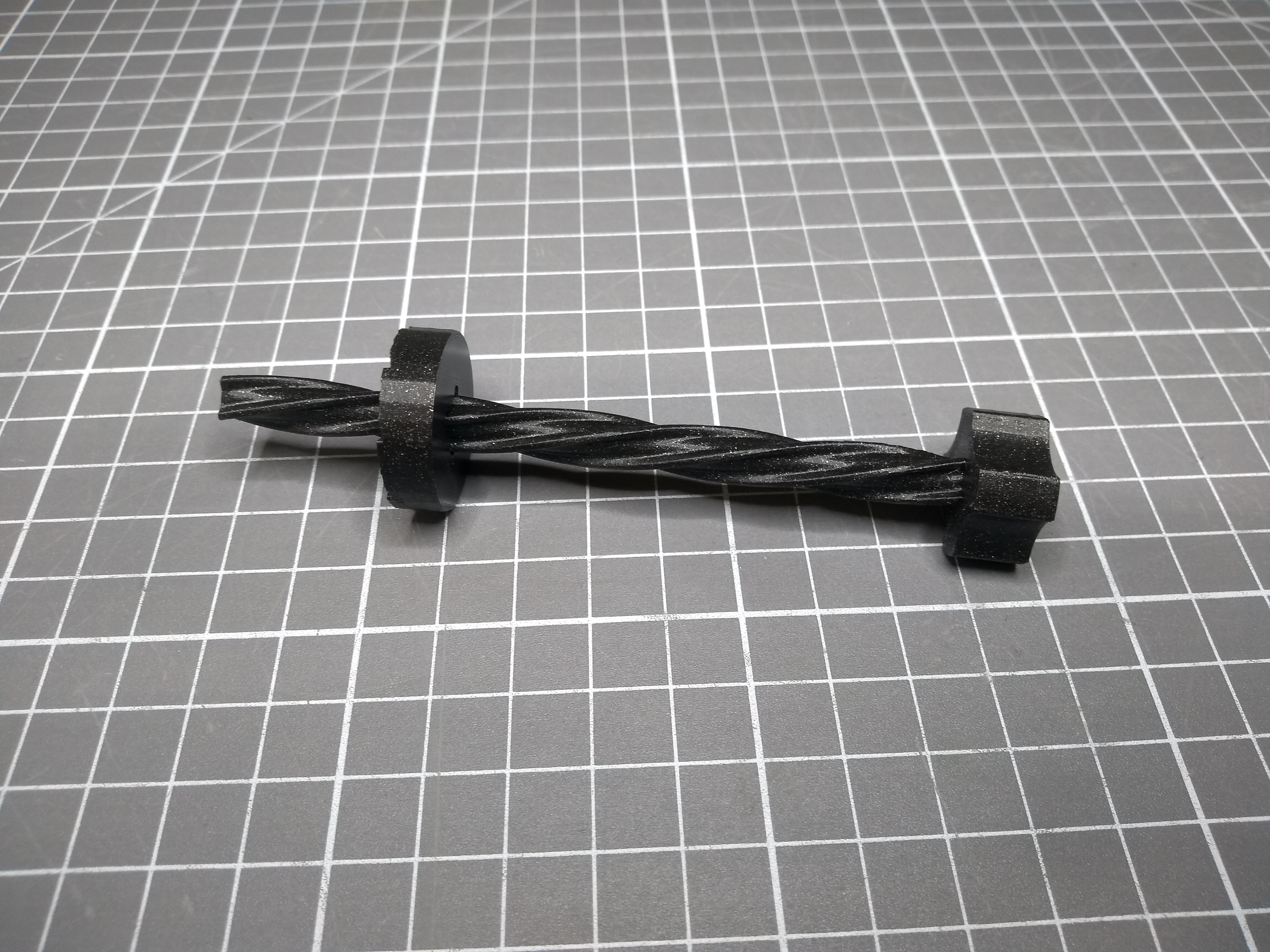
What you can see/hear here is that I'm pushing a lead screw into a hole in my mechanism, which accelerates an internal mass. The mass doesn't stop accelerating when I move the lead screw back out, and I can push it in multiple times to keep accelerating the mass.
So how did I come up with this? First I found out about the humming top, which is an old toy employing such a mechanism that rotates a metal body to create a sound from the airflow. I wasn't able to find out how those worked (nor did I have one at hand to take apart), but I eventually found this video by My Tech Fun, which presents a similar toy and explains the mechanism in detail.
I did create my own model, but basically copied his whole mechanism, so most of the credit goes to him. Also, his end result is a fully working toy, while I just built a proof of concept for the mechanism. I recommend you check out the video!
But back to my solution. At the center of the mechanism is a lead screw and a nut. This translates the linear motion of the lead screw into a rotation of the nut.
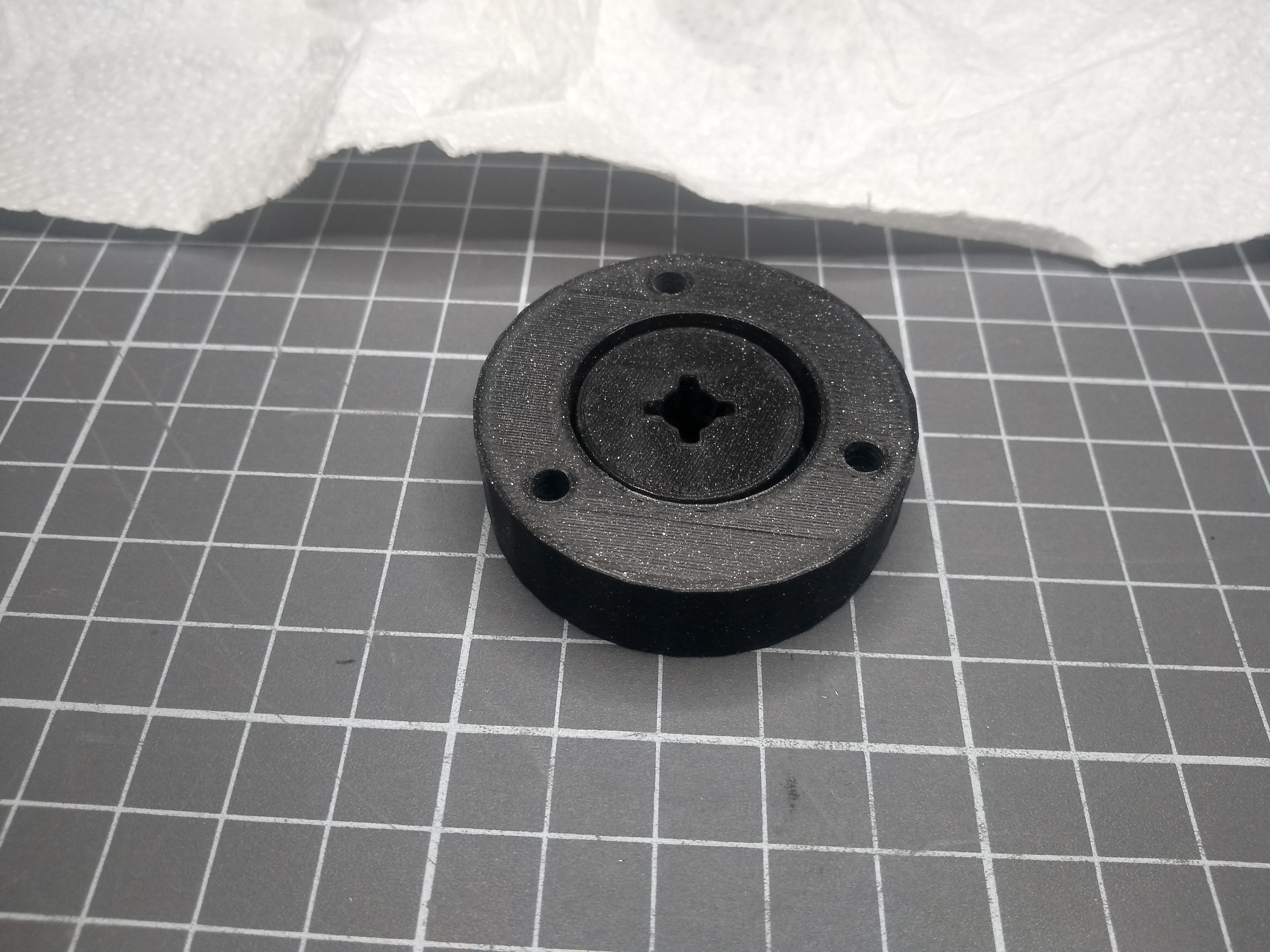
The nut goes into the rotor. Both the nut and the rotor have matching steps going in a circle. Those steps will engage when rotating in one direction, while just sliding over each other when rotating in the other direction. This is basically a ratchet.

The nut goes into the rotor like this:
And the lid goes on top:
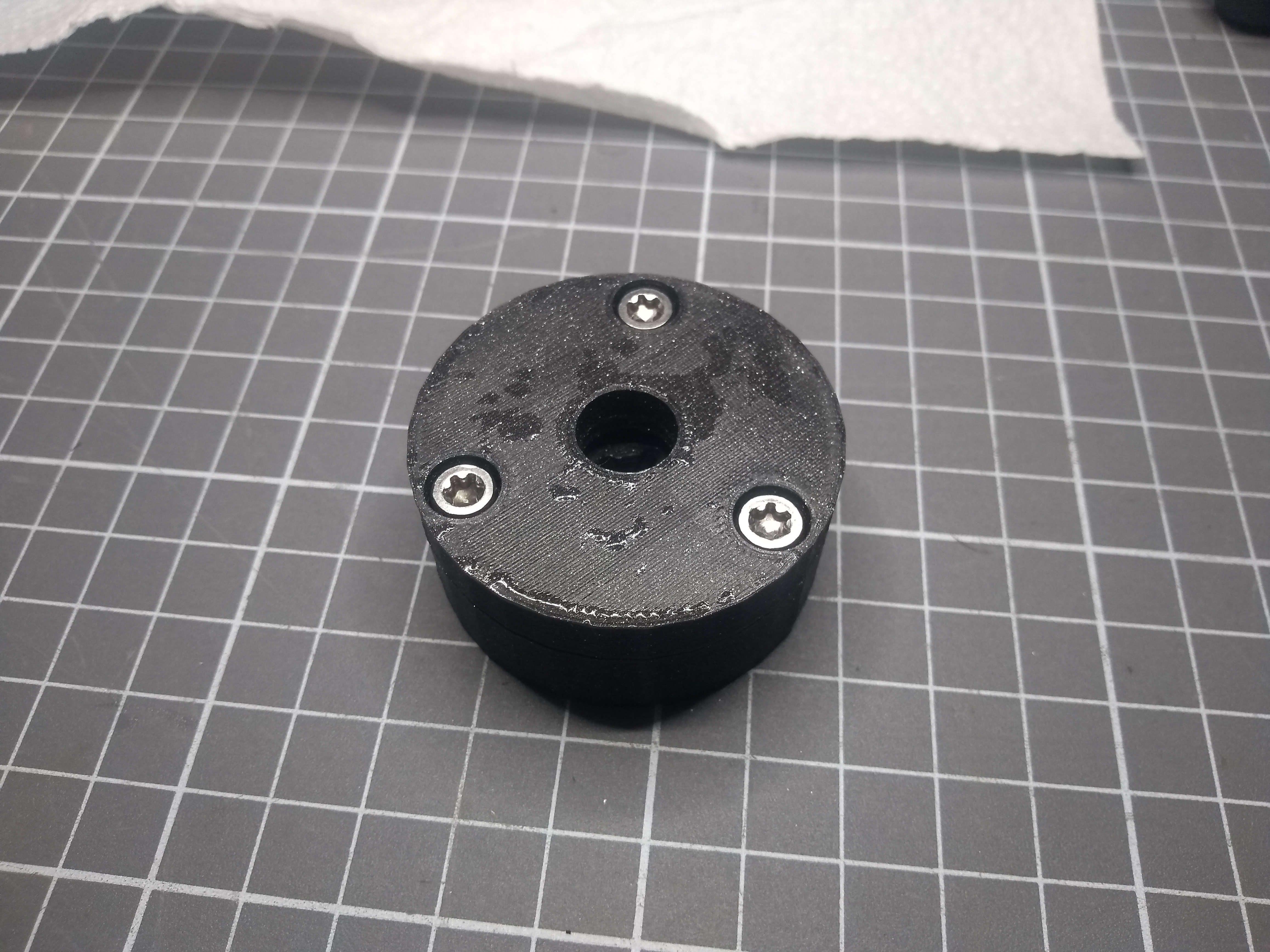
The core of the mechanism is basically complete at this point. When pushing the lead screw into the hole, the ratchet mechanism will be pushed together, and the linear motion of the lead screw will translate into a rotary motion of the whole rotor. If the linear motion is stopped or reversed, the rotor can still rotate, as the ratchet mechanism disengages.
Since I don't know whether this mechanism has a proper name, I'm calling it the ratchet clutch, which describes it well enough.
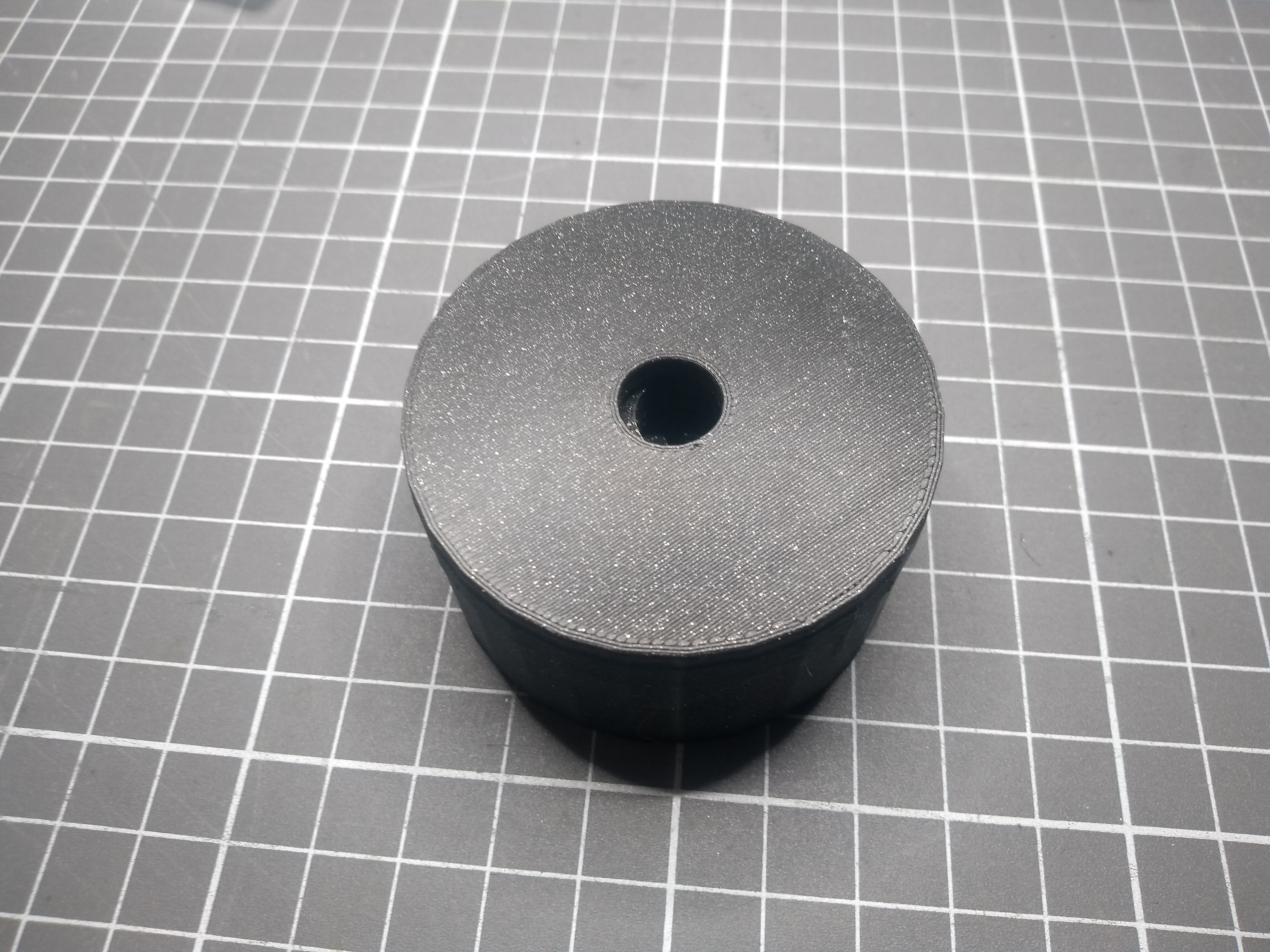
But we're not quite done yet: There need to be something to hold this in a way that allows for free rotation. For this, there's a simple housing.
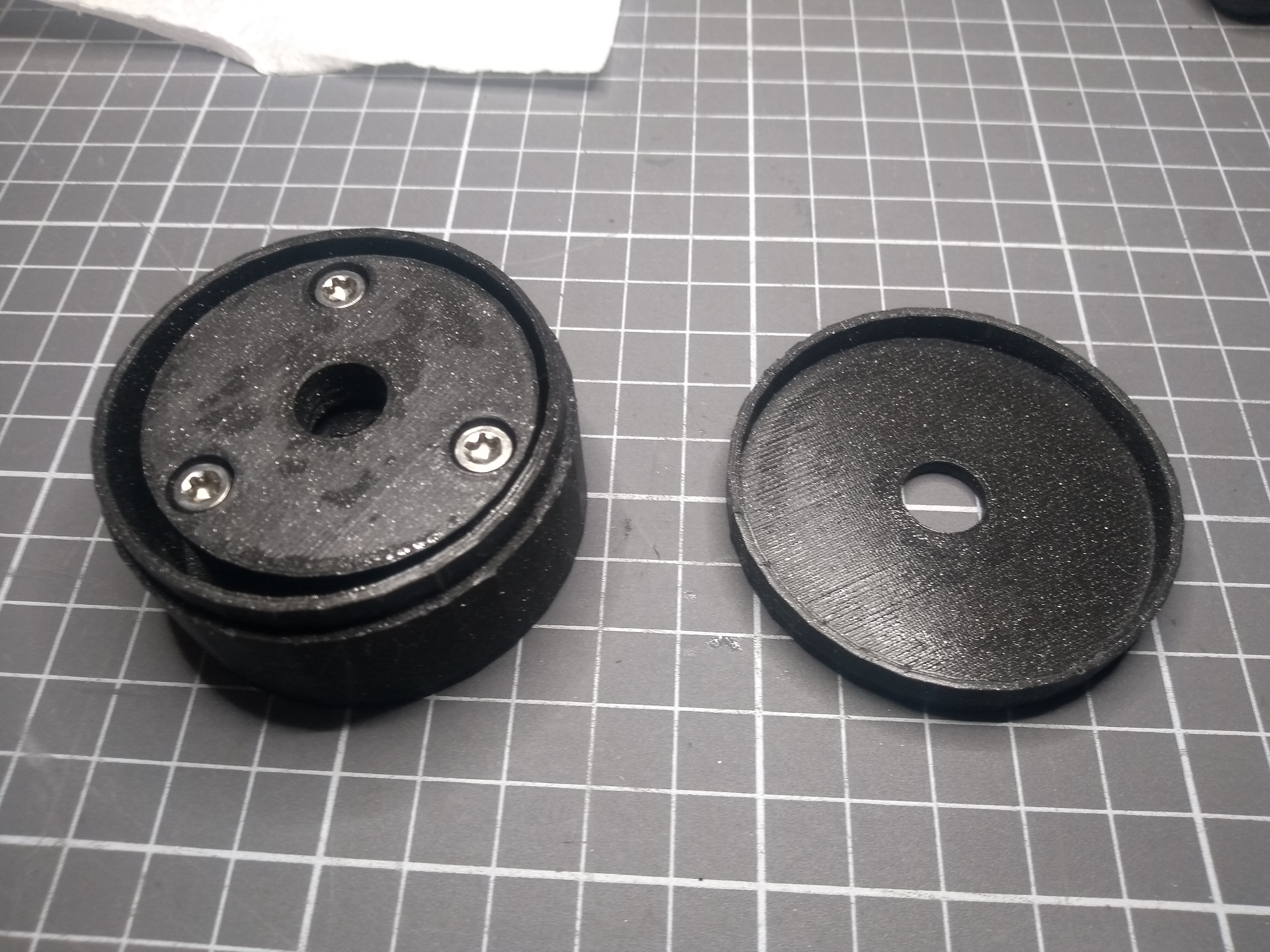
The lid is just pressed on top.
And that's basically it. One thing to note is that the whole thing is not very well designed, as there's too much friction between the rotor and the housing. It didn't work initially, but I was able to save it by applying some silicone-based lubricant to the rotor and housing.
There are a few things that could be improved: There's too much clearance between the parts, the lead screw and nut also fit a bit too loosely, and there's the problem with the friction of course. Another area of investigation would be to try another mechanism altogether. Some untimely YouTube recommendations have taught me about the freewheel and sprag clutch since finishing this, which look promising.
I have decided to not pursue this further, however. It works well enough as a proof of concept and I don't have a project lined up that would require this mechanism.
If you want to print this yourself, you can download my OpenSCAD model.